This HDMI mod replaces the AV port completely and offers an HDMI port instead for convenience.
The Installed HDMI mod does look like this:
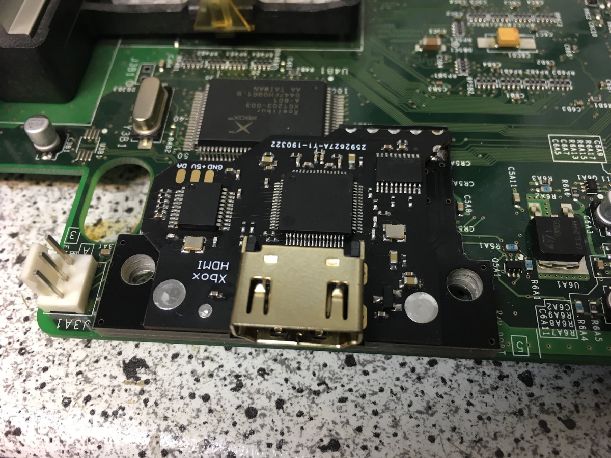
source N64freak on ogxbox forums
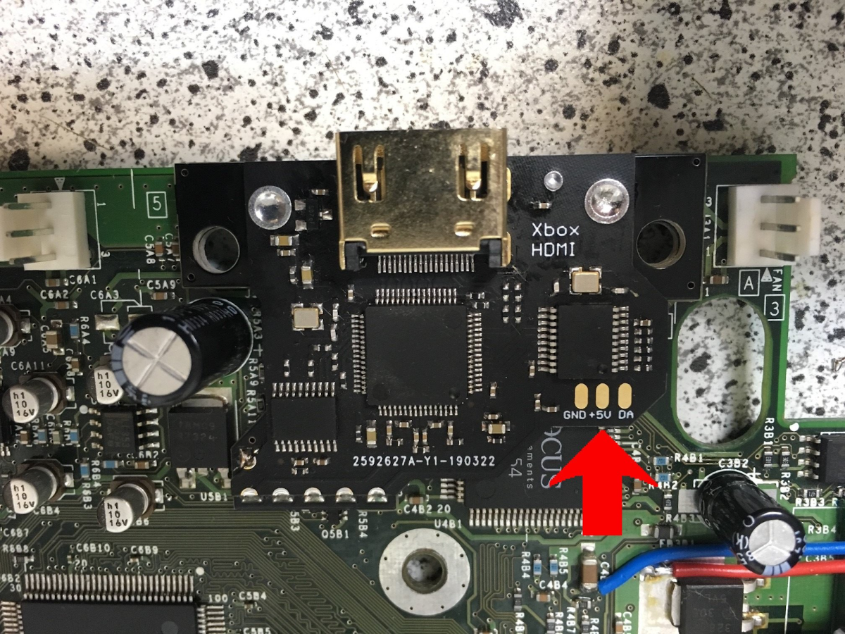
The HDMI mod does offer 5.1 sound through the HDMI port. If you don't need 5.1 (or your TV might not support it) you can simply disable 5.1 audio and get digital stereo audio instead. For those who want to add an optical output to there Xbox the HDMI mod does offer 3 solder points to add a TOTX178 optical transmitter.
To get the HDMI mod installed you first need to get the AV-port removed.
To get it removed you could either use a hot-air station or a heat-gun to remove it at once. But that would put a lot of thermal stress on the board!
The better and recommended alternative is to disassemble the Port and remove it one part at a time.
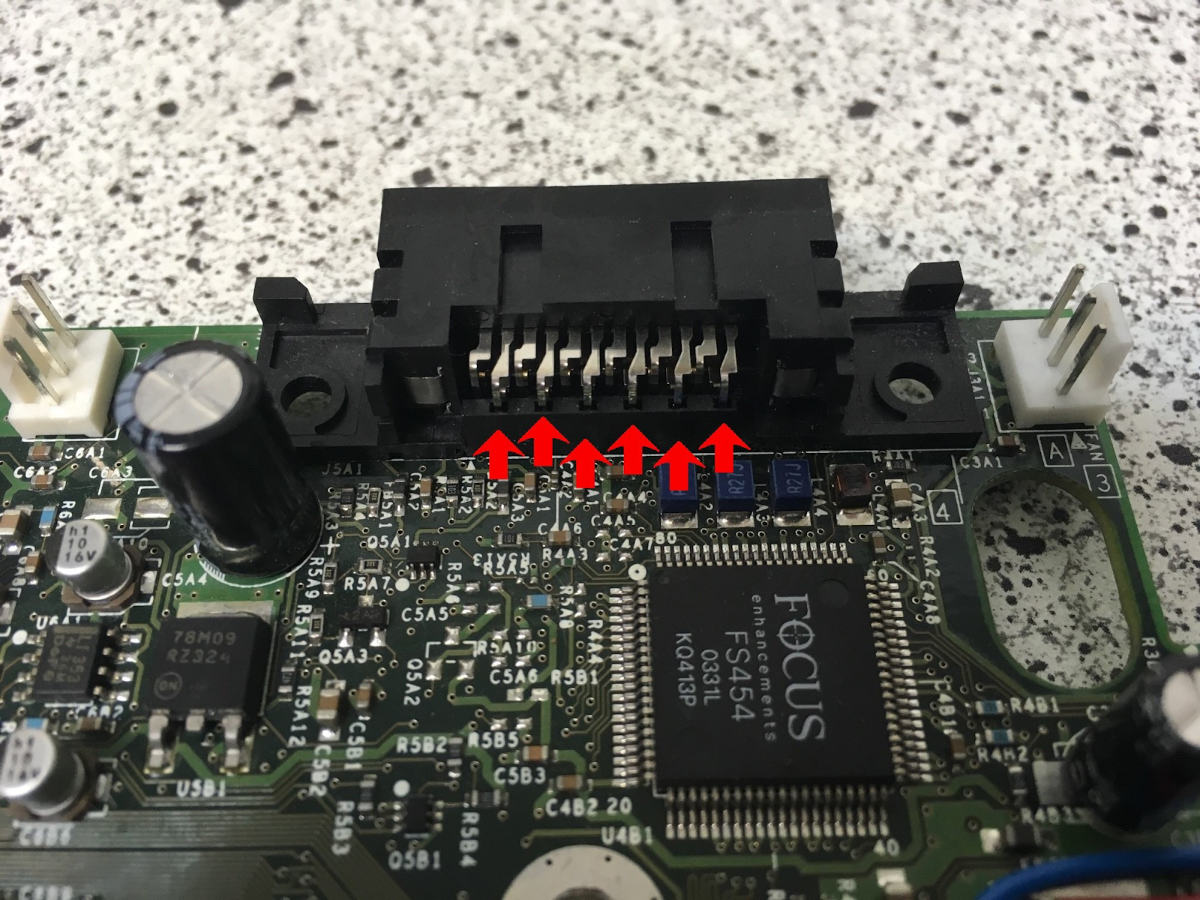
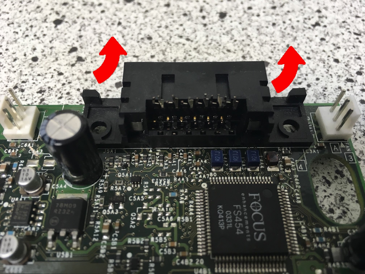
First desolder the Metal Tab holding it in place by heating them and prying the metal tab up to pull it out.
When the metal tab is removed take a sidecutter and clip off all the pins from the video port as they are what keeps the Port in place.
When they are clipped off you can take the port cover off by simply pulling it upwards.

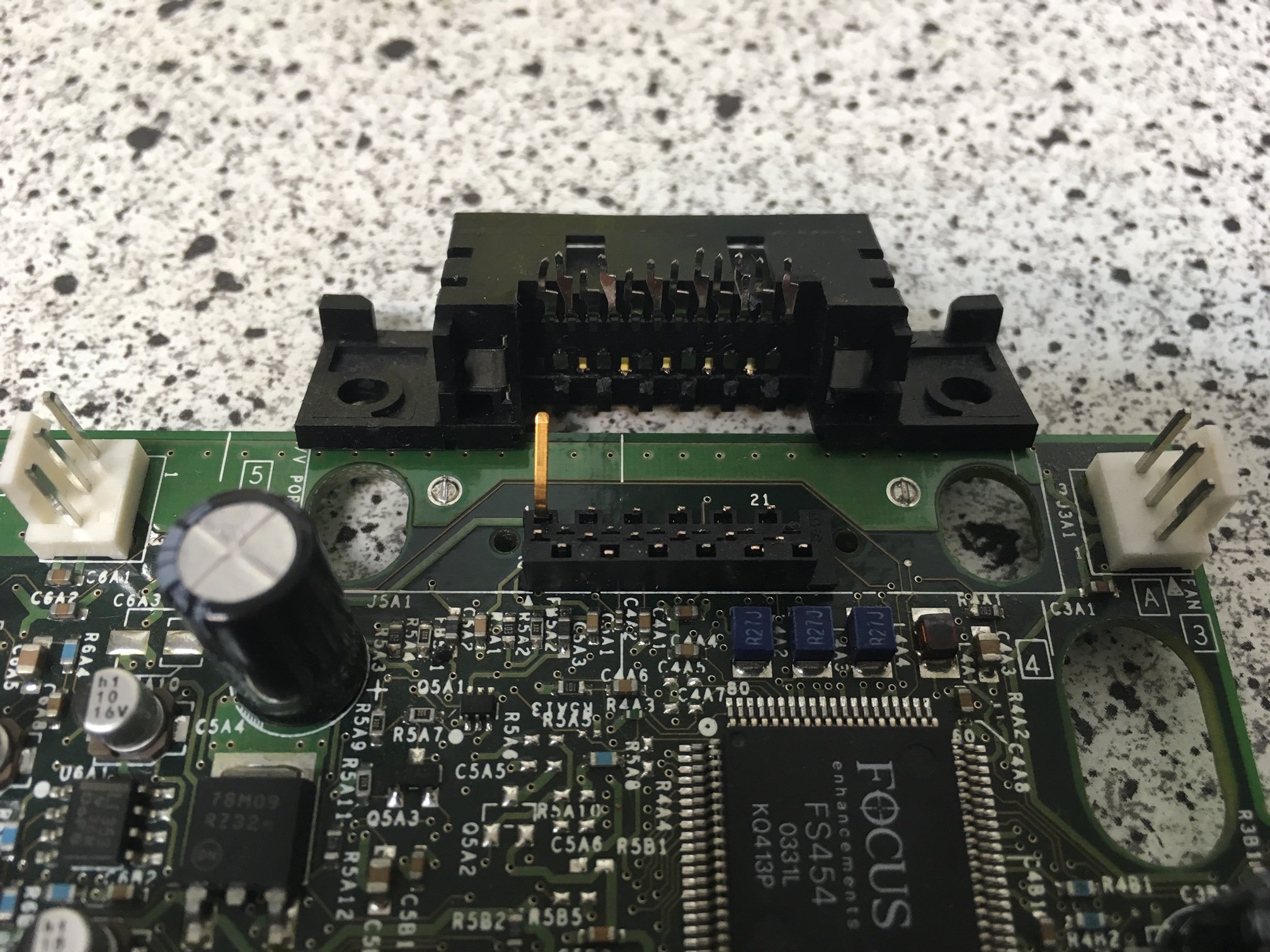
Next step is to remove the remaining plastic piece and desolder the rest of the pins and clean up the area a little.
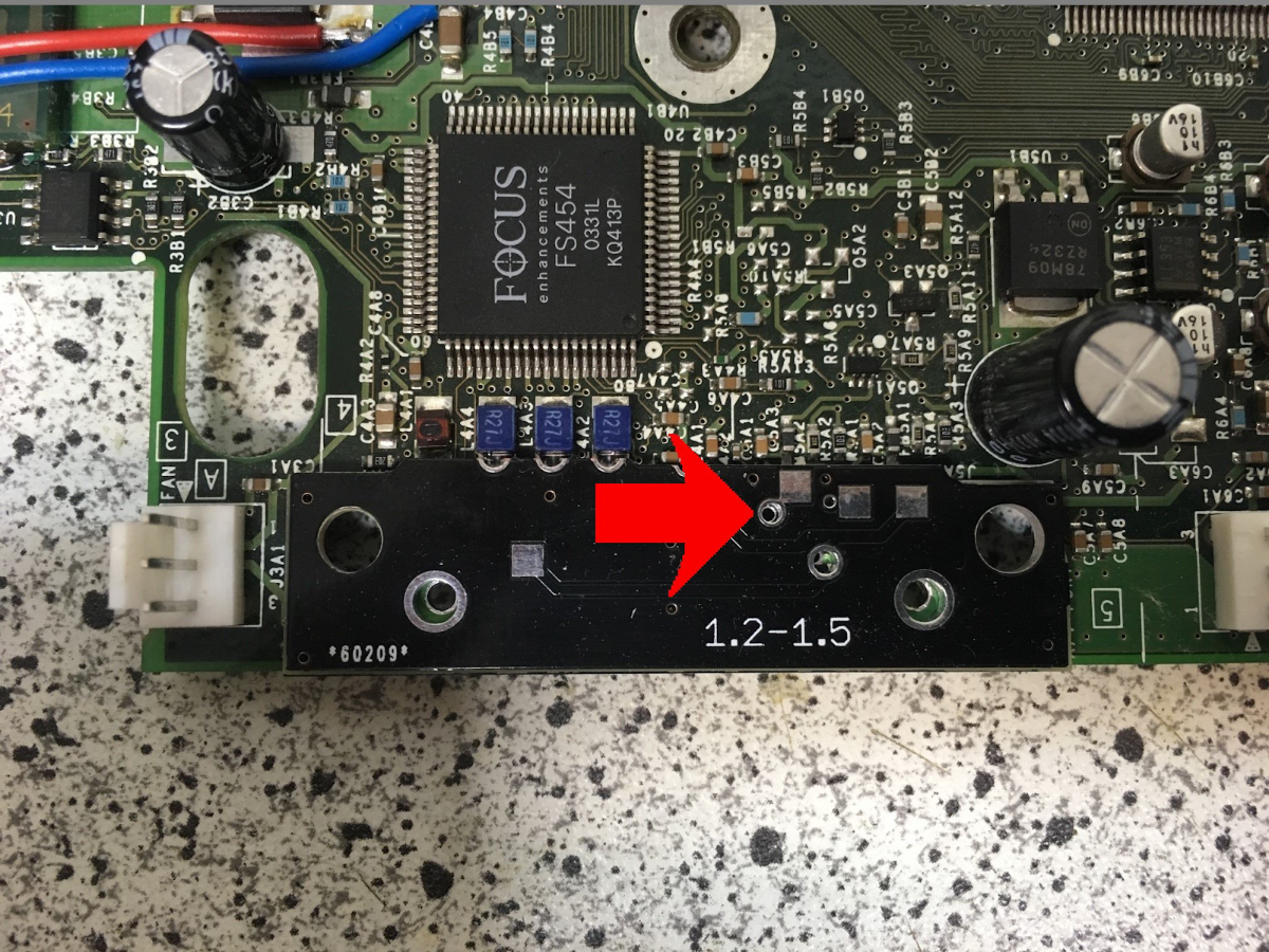
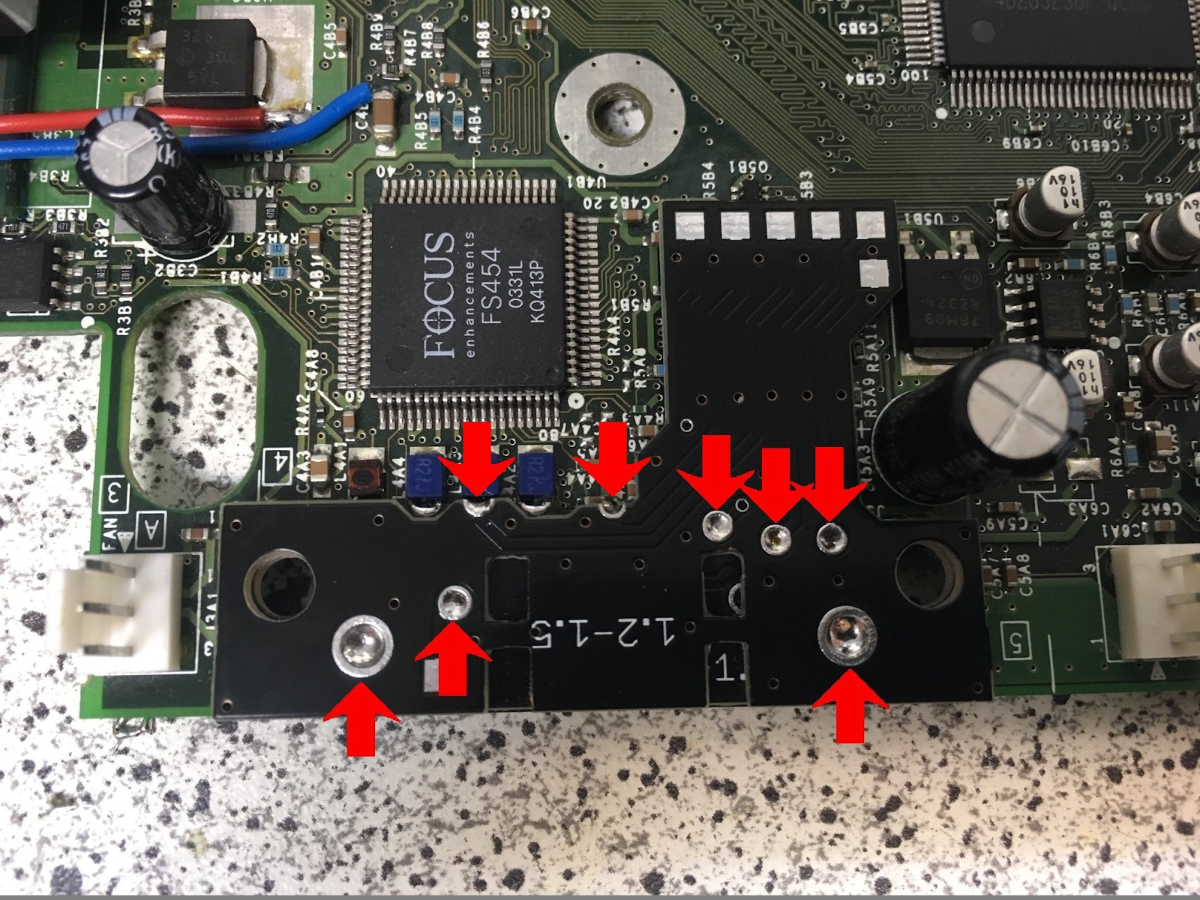
Position the first Adapter exactly as show in the photo. The red arrow marks the PTH that has to be alligned centered.
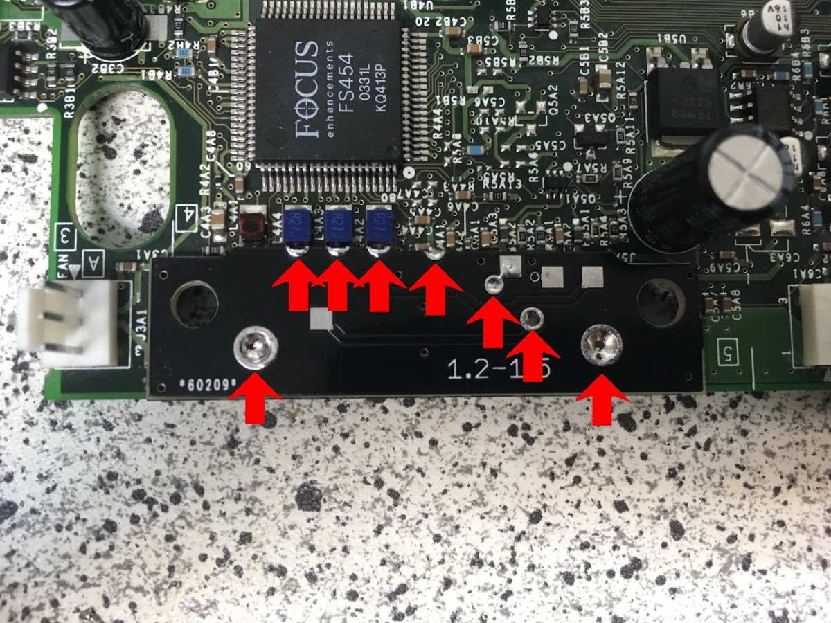
Once Positioned solder all the marked points down and make sure they are properly connected before continuing with the second adapter!
After soldering all the necessary points insulate the 2 soler points shown in green. A piece of kapton tape works well.
You should do this to be sure there's no unwanted connection occuring between the 2 adapter pcbs.

Next up is the second adapter. Just position it above the first adapter using the 2 big holes to allign them and solder down the marked points. Again check continuity before continuing with the next PCB!
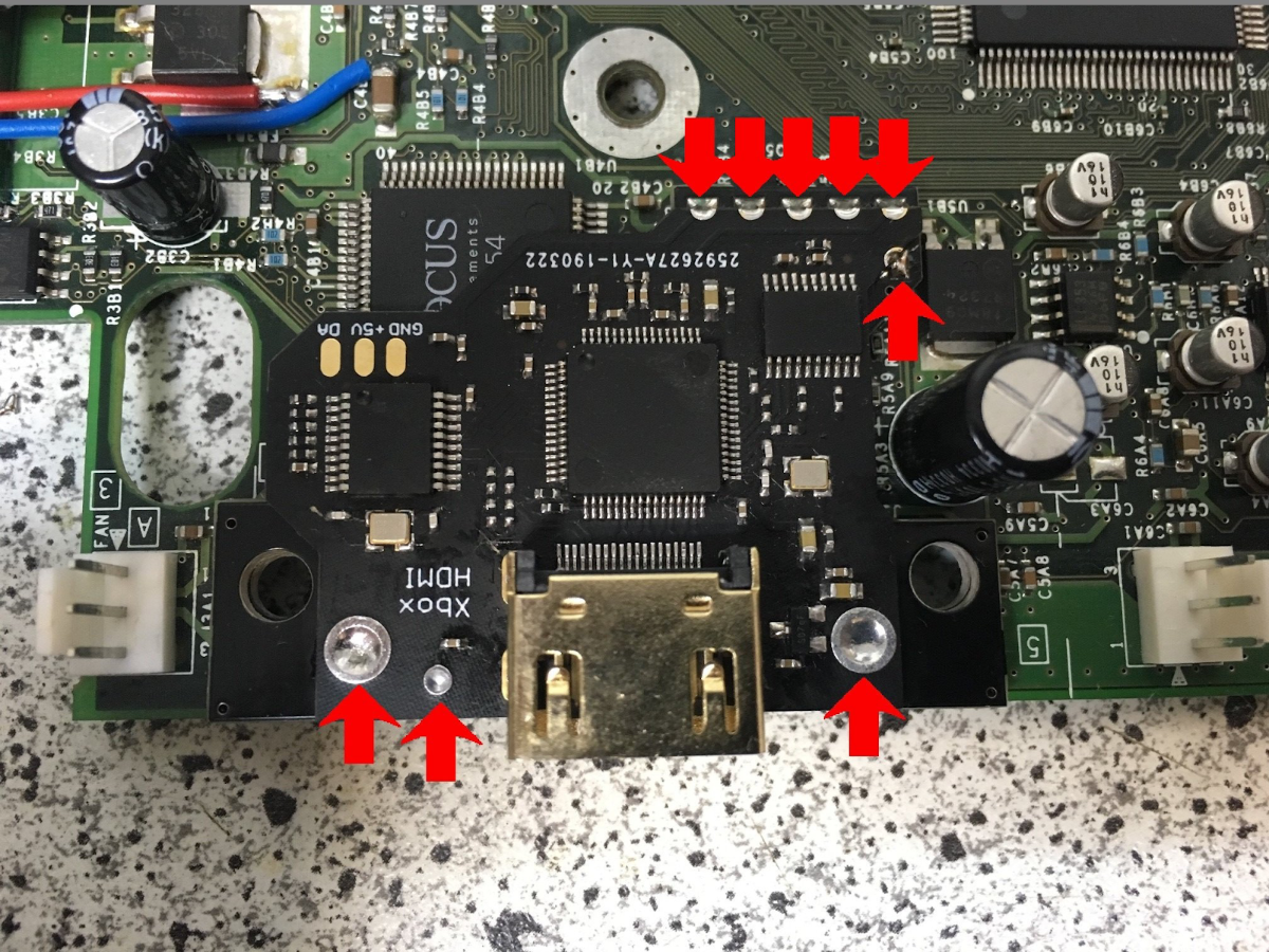
Last PCB is the HDMI mod itself. You need to position it slightly off centered on the second PCB. The HDMI ports pins will be position it correctly. Just solder down the points that are marked with the red arrows and the install is almos done!
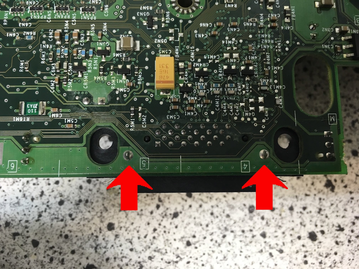
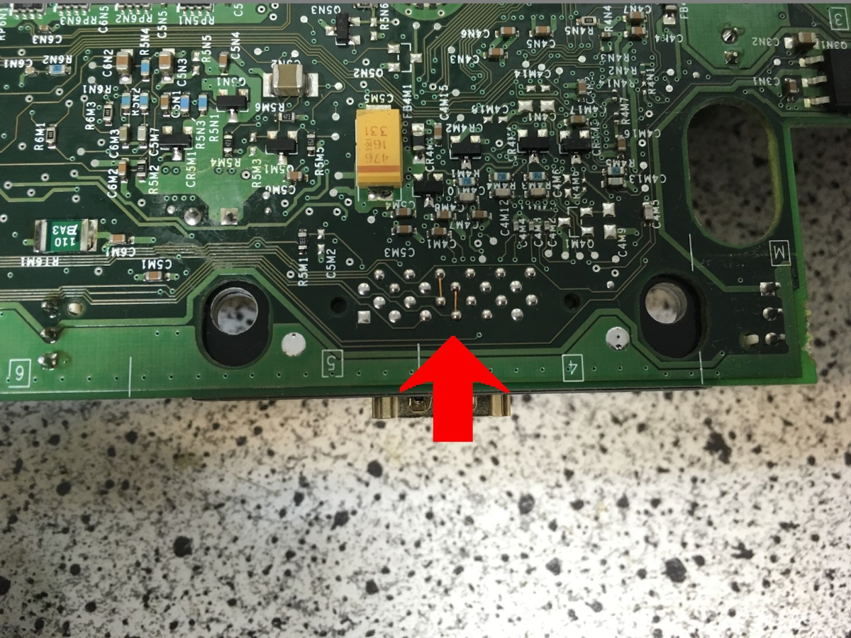
Last up is setting the Video mode. You need to add 2 small bridges on the bottom side of the PCB. Just solder in the 2 bridges and the video mode is set correctly!
If you want to use the optical out you can easily add a toslink port to the HDMI mod by simply soldering a Transmitter to the 3 marked pins.